CM-Cabinets Library User Guide
Custom Tables are very useful additions to the capability of CabMaster, allowing you to develop your own custom machining and apply it to various parts of cabinets.
See Library Basics topic on Table QLT Editor which explains how to locate Lookup Tables and other File Locations.
 Click here for a YouTube Play List
  of FREE step-by-step tutorials (see list below).
For discussions on the various ways Custom tables can be used, follow the links under See Also.
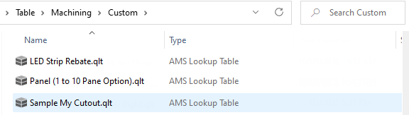
Custom tables are stored under <your CabMaster folder>\Table\Machining\Custom folder
Table\Machining\Custom folder
This is where all your Custom Tables are stored, and accessible from the Cabinet Machining > Custom page while editing a cabinet.
If your custom file already exists you can simply edit it or you can create a copy of an existing file (i.e. Copy/Paste to duplicate file and rename).
You can then use the CabMaster Table QLT Editor or any general spreadsheet application to amend/edit your custom file to your requirements.
A custom table can have up to 30 rows and, if you need to, you can use every single row in a custom table!
Be aware, however, that custom tables are split into different usable sections :-
This does not mean that you can only have a maximum of 10 drilling holes from each custom table, or 10 routes with a radius or 10 routes with a poly arc.
Read on, and you will see there are methods of getting so many more!
Each column has a Heading and an associated Value Type, which is defined by using the drop list under it, that will be put in each column. Most commonly used Value Types are :-
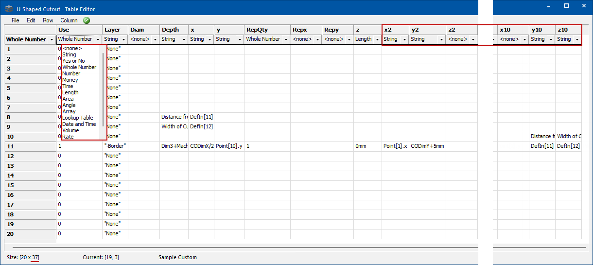
Example : Column Headings and Value Types
This example uses Rows 1-20 and Columns x, y, z are repeated (i.e. x2, y2, z2 to x10, y10, z10) making a total of 37 columns.
The drop list shows the available value types that can be applied to each column.
As shown, by default the Use column is normally set to Whole Number as it requires a 0 or 1, whereas the Layer column is set to String as that column will contain a string of text.
The following is an explanation of each column heading, associated value type and use of cells.
Determines whether the row is applied to the machining in CabMaster and is normally set to Whole Number as it requires a 0 (off) or 1 (on).
However, there may be times when this column may need to be set to a conditional statement, in which case it can be a String.
- Example : If CabWidth>600mm then 1 else 0
- which would make the Use column hold the value 1 if the cabinet width is greater than 600mm.
The layer name that is used for nesting.
This links the machining to the toolpath in your nesting package (i.e. EzyNest or EnRoute). The value type must be set to String, and the layer name must be in quotes, e.g. “Screw 3mm”.
The diameter of the tool used for drilling. Used in Rows 1-10 only.
The depth of the cut.
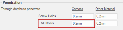
If the drilling/routing is to go all the way through the sheet, this would normally be set to Dim3+MachPenetrateCarcass
- Dim3 will identify the thickness of the material
- MachPenetrateCarcass will identify the Carcass All Others value entered in Mach. General > Tool2 page.
- See notes on Variables below.
Mach.General > Tool2 page - Click to Expand
Rows 1-10: Not used.
Rows 11-30: Set to either Yes or No.
- Determines whether a route will be a closed shape or not.
- Yes = Open Shape (default if column does not exist or is blank)
- No = Closed Shape (i.e. the last point automatically joins to the first)
- If it is to be a closed shape, it automatically adds an additional route from the last route point back to the first route point.
Rows 1-10: The horizontal position of the first drilling point.
Rows 11-30: The horizontal position of the first point of the route.
Rows 1-10: The vertical position of the first drilling point.
Rows 11-30: The vertical position of the first point of the route.
See note on Part Sizes below.
The number of times the drilling or routing will be repeated on the sheet. If there is no repeat necessary, set this to 1.
If it is repeated once, it will need to be set to 2 , as there will be two instances of this drilling or routing, offset by the Repx and Repy columns.
The horizontal offset for where the drilling or routing will be repeated. If the repeat does not require a horizontal offset, set this to 0 .
The vertical offset for where the drilling or routing will be repeated. If the repeat does not require a vertical offset, set this to 0 .
If both Repx and Repy are used, the repeat will be positioned diagonally as it applies to both the horizontal and vertical offset to the repeat.
Rows 1-10: Suppression of drilling.
- Determines whether the drilling location specified in the X and Y columns will drill or not.
- Set this to 1 to drill or 0 to not drill.
Rows 11-20: Radius to the next point.
- Set this to 0 to make a straight line to the next point.
- Remember to set this to a negative value if it is to be an inward radius.
Rows 21-30: PolyArc (not covered in this document).
Rows 1-10: The same definition as columns x, y and z above.
- Each numbered column (i.e. x2, x3, x4, etc) gives an option of another drilling point.
Rows 11-30: The same definition as columns x, y and z above.
- Each numbered column (i.e. x2, x3, x4, etc) gives an option of another point of the route.
It is important to use the columns in order, not skipping any. For example, if you have 4 drilling points, use (x y z), (x2 y2 z2), (x3 y3 z3) and (x4 y4 z4).
If the x,y coordinate of the point you are needing to route or drill is measured against the size of the part, you can use CODimX and CODimY. These represent the X and Y size of the current part.
If you need to have a closed-shape route, the alternative to using the Open column is to set your last route point to the same position as the first route point. This is easiest achieved by putting point[1].x in your next unused X column and point[1].y in the Y column.
Similarly, you can reference any other column’s route point by changing the number [1] to the number of the column you are needing to reference.
This can be particularly useful when a route has a closed shape but also includes points that are not part of the closed shape.
Example :-
If required, there is a method of referencing your CabMaster’s Drawing and/or $cabinet properties from within a custom table.
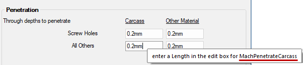
Simply hold the mouse cursor over a textbox and, as shown below, a message will be presented that includes a ‘variable’ name. This can then be used as a value in your custom table.
This example shows that the Carcass All Others value is 0.2mm and is controlled by the variable MachPenetrateCarcass. This particular variable is useful when specifying values for the Depth column.
When a variable has an addition on the end with letters in square brackets you will need to surround the bracketed letters with apostrophes.

Cabinet Machining > Machining page - Click to Expand
For example, the variable name MachBuildEndCam[EnR] would be put in the custom table as MachBuildEndCam[‘EnR’]
The addition of apostrophes is not required if the square brackets contain only numbers.
Click here for a YouTube Webinar Play List which covers the topics below, providing FREE step-by-step tutorials that will help you understand the basic ins and outs of custom tables and more advanced custom table options in CabMaster Software.
Webinar 1: Discusses how to use custom tables to create LED strip rebates and helps you understand the basic ins and outs of custom tables and more. [52:47 mins]
Webinar 2: Discusses how to create custom tables for boring, holes and drilling, and helps you understand the basic ins and outs of custom tables. [37:07mins]
Webinar 3: We will dive a little deeper into custom tables and show you how to use quantity formulas to your advantage. [43:04mins]
Webinar 4: We will walk you through more custom table options and show you how to use custom tables to make an adjustable rebate handle. [57:42 mins]