CM-Cabinets Library User Guide
Customers may require additional machining in components than that provided.
The Mach.Parts > Special page of the Catalog/Drawing Properties allows for this without the need for customisation or waiting on new library releases, up to four (4) sets of holes can be set up for each of the components listed below.
The instructions for these come from special tables.
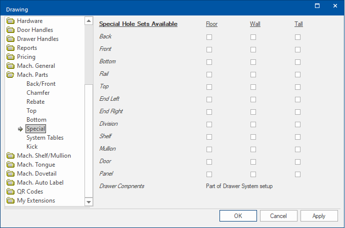
For each component, there are different set ups available for the three cabinet types (FLOOR, WALL and TALL), as selected on the ‘Special page’ and also the style of cabinet Standard’ ‘Corner’ or ‘Angled’ designated in the Lookup Tables discussed below.
Drawer components are handled separately [See Drawer Runner Tables Explained]
If the ‘special’ holes are to be used for a component then the appropriate box should be checked and the ‘special’ tables set up as. Within the tables you can specify different settings for the cabinet style (Standard, Corner and Angled).
When checked the appropriate specials table is looked up in <your CabMaster folder>\Table\Machining\Specials
EndLSpecials.qlt
Example of table in Specials folder.
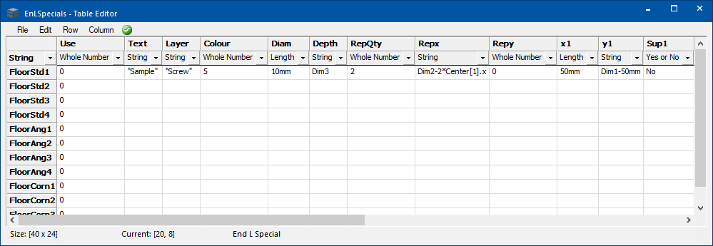
The tables contain 4 rows for each combination of Cabinet Type and Style (e.g. “FloorStd1”, “FloorStd2”, “FloorStd3” and “FloorStd4” for the Floor Standard cabinets).
For each row there are a number of columns, which define the machining (note that these are assumed to be controlling a “multibore” machine step).
Each row allows up to 5 holes to be defined along with a repeat quantity and repeat offsets. The contents of any cell of the table can either be a specific value or an acceptable CabMaster formula. The columns directly relate to the corresponding machine step settings shown below.
| Column | Details | Example |
| Use | 1 = Yes 0=No | |
| Text | Optional text that if used will prompt the user with a checkbox | '"Lift up Stay"' or '"Sample"' |
| Layer | Machine layer name |
'"Screw"' for Screw hole. Note that as this text field is not a formula, it has single quotes around the double quotes, as does the Text Layer above. |
| Colour | Colour of DXF layer | 0 = Black; 5 = Blue |
| Diam | The diameter of the hole | 10mm |
| Depth | The depth of the hole | 14mm - to drill through the material use "Dim3" |
| RepQty | Repeat quantity | 2 (Whole number) |
| RepX | Repeat offset in the x direction | 0mm or formula "Dim2-2*Center[1].x" |
| RepY | Repeat offset in the y direction | 0mm |
| x1 |
X coordinate 1 [Same for x2, x3, x4, x5 columns] |
50mm |
| y1 | Y coordinate 1 | "Dim1-50mm" |
| Sup1 | Suppress hole 1 Yes or No | No |