CM-Cabinets Library User Guide
This topic discusses the Hardware > Legs page of the Cabinet Properties. Five different leg hole configurations are supported.
These controls only affect individual floor cabinets in your current drawing.

Turn on/off the use of cabinet legs (Feet) on the current cabinet.
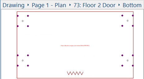
Positioning of Leg Holes
- One set of leg hole is placed in each of the four (4) corners of a cabinet.
- Additional sets of leg holes are placed along the length of a cabinet as the width increases.
- The Separation length (in the Offset group box) determines when this addition occurs.
- One set of leg holes is placed either side of an internal corner.
- The corner leg holes are replaced by pairs of leg holes when a corner is chamfered.
See Drawing topic for more details and examples on Positioning of Leg Holes.
Corner cabinets - see the Cabinet Machining > Machining page for options to Override Back Cnr legs.
Tick the Machining check box to add drilling and all required machining.
If you tick Opposite Face, then machining on the "opposite" face of the part will be outputted with "-opp" added to the end of the layer name.
The machining diameter and depth of the drill holes is set on the Hardware > Legs page of the Drawing properties.
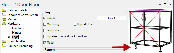
When enabled, legs are only presented at the front.
Example
In this example, only the front 'Adjustable Leg Black' are visible in the preview. (Note the kick has been removed)
Tick the check box to enable.
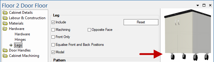
In-built leg models are available and can also be displayed in 3D. Refer to the Hardware > Legs page of the Drawing properties.
Tick the Model check box to enable. This example shows the 'Caster' legs displayed in the preview. (Note the kick has been removed).
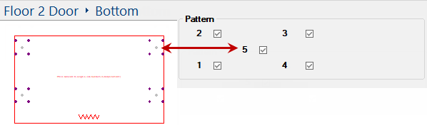
This is the pattern of drill holes. You can have up to five (5) drill holes. Simply tick the applicable check box/s.
Note that this is only applicable if the Machining option is ticked.
The defaults are set on the Hardware > Legs page of the Drawing properties.