CM-Cabinets Library User Guide
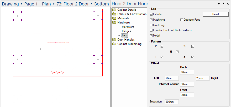
The Hardware > Legs page of the Catalog/Drawing Properties provides the ability to set current job defaults.
Five different leg hole configurations are supported. If legs are required on the majority of floor cabinets in your current drawing, then this is where you should set the parameters. These options can be overridden for individual cabinets - see Cabinet Properties.
 click on the area of interest.
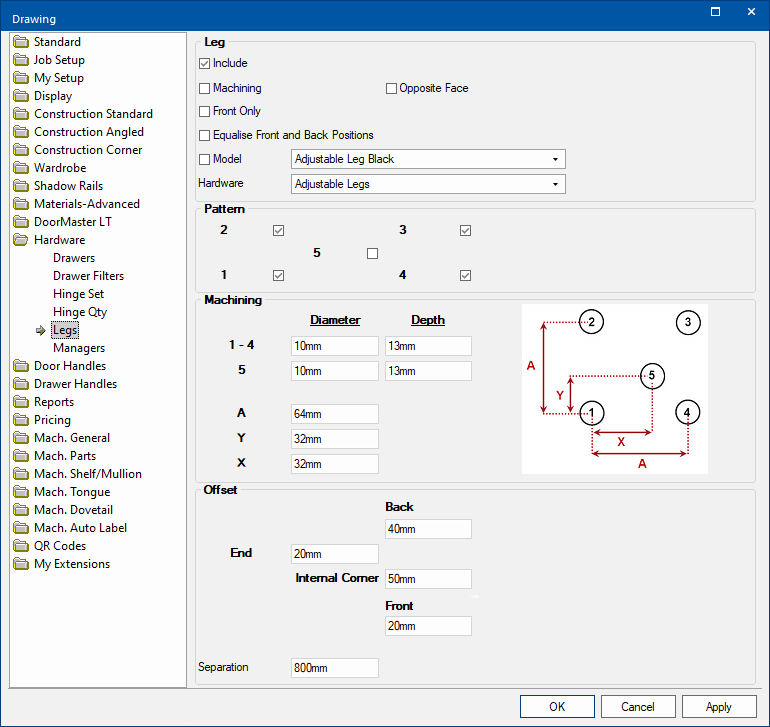
If you use cabinet legs (Feet), then tick the Include check box.
Positioning of Leg Holes
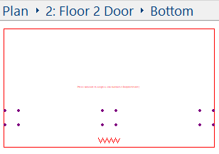
- One set of leg hole is placed in each of the four (4) corners of a cabinet - see example.
- One set of leg holes is placed either side of an internal corner.
- The corner leg holes are replaced by pairs of leg holes when a corner is chamfered.
Example : Internal Corner and Corner Chamfer
The example of a Floor Corner cabinet :-
- First example shows cabinet, using only one drill hole (see Pattern), but has a set placed either side of the Internal Corner .
- Second example is the same cabinet with Chamfered corners added and pairs of legs automatically applied.

Click to view Cabinet Details > Options page for Corner Chamfer options
Floor corner cabinets: Options to Override Back Cnr legs and turn them Off or Move them a specified distance, are available on the Cabinet Machining > Machining page.
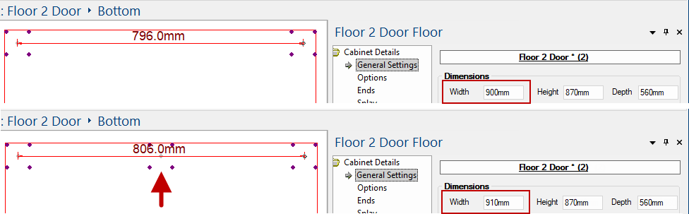
- Additional sets of leg holes are placed along the length of a cabinet as the width increases - see Separation.
Example : Width increase
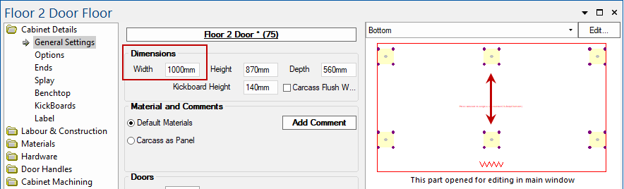
Floor cabinet with an increased width from standard 750mm to 1000mm. An additional set of legs has been added.
Tick the Machining check box to add drilling (see Diameter and Depth) and all required machining.
If you tick Opposite Face, then machining on the "opposite" face of the part will be outputted with "-opp" added to the end of the layer name.
When enabled, legs are only presented at the front.
Example
Tick the check box to enable.
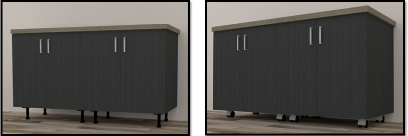
Legs (Feet) can be displayed in 3D. These feet can be displayed as plastic feet or casters and include all required machining.
Tick the Model check box to and select one of the in-built leg models from the drop list.
Location of Models : <your CabMaster folder>\Bitmap\Hardware\Leg\Model folder
Example of 3D Display

Adjustable Legs are accessed using the Hardware Manager and can be priced for reporting purposes.
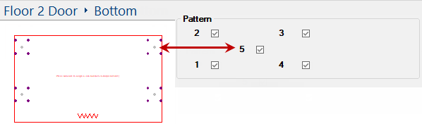
This is the pattern of drill holes. You can have up to five (5) drill holes. Simply tick the applicable check box/s.
The diameter and depth of the drill holes 1 - 4 can be set independently of the drill hole 5.
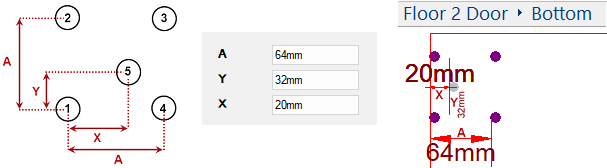
An independent setting is provided for drill hole 5 because it is generally drilled through, allowing for height adjustment with a screw driver from the inside of the cabinet.Edit box A is the equal distance between drill holes 1 - 4. In the following example, A is 64mm.
Edit boxes for X and Y specifies the position in relation to drill hole 1. In following example, X is 20mm.
Drill Hole Numbering
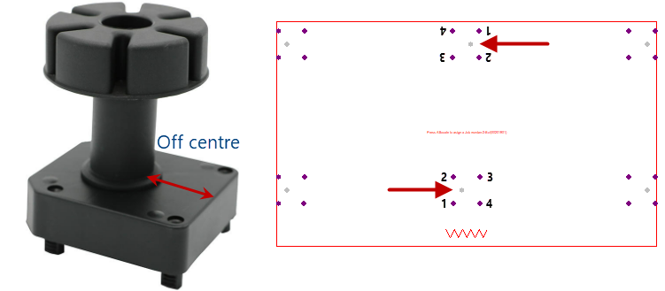
Legs generally are set in the centre of the screw-on base. This is not always the case, however, and may require the leg to be rotated to face the edge of the part that it is to be attached to.
Example
Shows the adjustable leg set off centre on the screw-on base. This would require the leg to be turned, as shown.
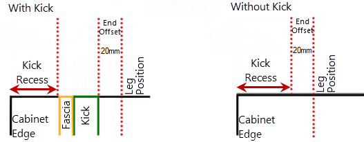
Offset is either from the inside of the kickboard (if present) on that face or the edge of the cabinet (without kick).
End
The distance from the inside of the End Kickboard to the centre of the main hole – for front and back leg holes.
The presence (as well as thickness) of both the Kick and Fascia are taken into account. So, if the Kick and Fascia are NOT present then the End Offset is be taken from the Kick Recess and not from inside of where the Kick would have been.
Back
The distance from the inside of the Back Kickboard to the centre of the main hole – for back leg holes.
Front
The distance from the inside of the Front Kickboard to the centre of the main hole – for front leg holes.
Internal Corner
The distance from the inside corner point to the main hole – for front corner leg holes.
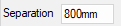
Additional sets of leg holes are placed along the length of a cabinet as the width increases. The Separation length determines when this addition occurs.
Example
As the cabinet width increases, the distance between the centre of leg holes (1-4) is compared to the Separation length.
In this example, the Separation is 800mm, so when the distance between the centre of leg holes is greater than 800mm, additional sets of legs are added.
Note: Hole 5 has been turned on for illustration (to show centre) but separation length is NOT calculated from X,Y coordinates of Hole 5.
At Cabinet level, you can override these settings on the Hardware > Legs page.