CM-Cabinets Library User Guide
The Const page (short for Construction) allows the user to define whether the components are manufactured on the Saw, Flatbed, are Purchased or some other method and how they are constructed – whether using Screws, Cams, Tongue & Groove, Nails or Another Method.
An output path for any machined component is then defined on the Const2 page.
The Mach.General > Const page in the Catalog/Drawing Properties allows you to define settings for Construction and Manufacturing of components.
 click on the area of interest.
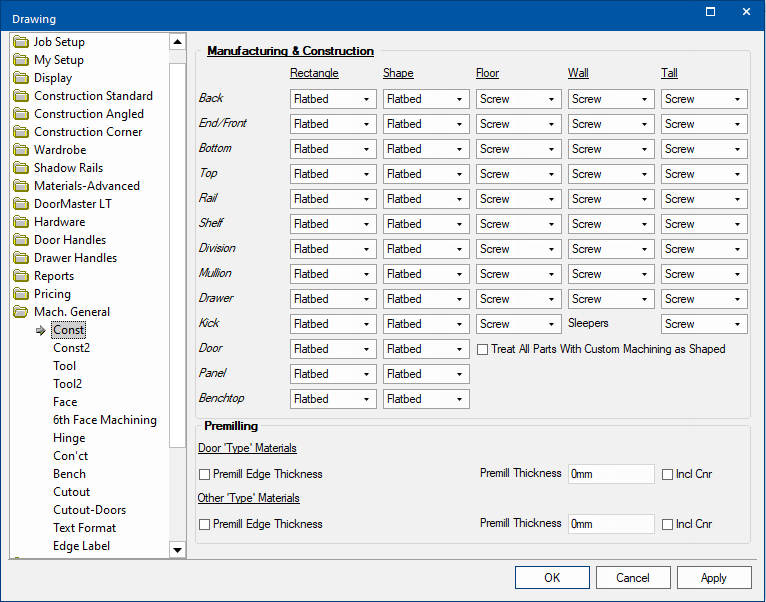
Settings are available for when a component is rectangular or shaped.
The drop lists allow you to select how the component is to be manufactured...
For each shape, a setting is available for each type of component i.e. Ends, Backs, Bottoms etc.
The Treat All Parts with Custom Machining as Shaped checkbox allows you to enable or disable this function.
Different construction method settings are available for Floor, Wall and Tall cabinets.
The drop lists allow you to determine what construction method is used for each component. The values available are...
For each cabinet type a setting is available for each type of components i.e. Ends, Backs, Bottoms etc.
The Other setting is used to identify special construction techniques. This is only currently being utilised for backs, where ‘Other’ identifies that the backs are rebated into the ends and/or tops (and bottoms).
Panels and doors do not require Construction settings.
The offset and diameter can be changed on the Mach.General > Tool page.
A Premilling edge-bander removes a specified amount of material from the edged sides of a board. In CabMaster the part premilling allows parts to be oversized by the amount your edge bander will remove when edging parts.
Example
A 100mm x 100mm part with 1mm Edging all around will have a cut size of 98mm x 98mm.
The same part with premilling of 1mm will have a cut size of 100mm x 100mm.
The amount CabMaster takes off an edged side can be defined in one of two ways :-

Enabling this option will always add on the edge thickness to the edged side.
An edge that is 1mm thick will add 1mm to any side edged with it and a 2mm would add 2mm and so on.
Premill thickness lets you define a fixed amount to remove from each edged side. This fixed amount will then be added to all edged sides.
With a 1mm premill thickness, 2mm edge tape would add an extra 1mm to edged sides as would a 3mm tape and so on...
You can specify a separate premilling setting for Door 'Type' Materials and all Other 'Type' Materials .
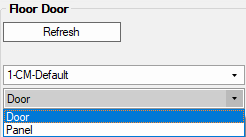
Door type materials are defined in the Catalog/Drawing Properties located on the Materials-Advanced > Door page using the Door filter, as shown.

The Inc Cnr checkbox allows you to either enable or disable premill allowances on edges with an internal corner (e.g the front of a corner shelf).