CM-Cabinets Library User Guide
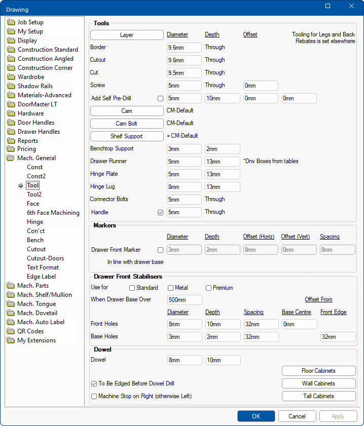
The Mach.General > Tool page is used to specify the common tooling requirements for the supported machine steps in the Catalog/Drawing Properties. Routing toolpaths are also supported e.g. a preconfigured settings file (.CDF) can be imported for the Peanut-1 connectors
To locate information about any part of the following image,  click on the area of interest.
This button opens the Layer Management page to allow you to view/modify the settings.
The Diameter of the tool used for each of the machine steps. The actual tool size is controlled by the strategy selection in EzyNest and the actual tool fitted to the machine. However, the diameter selected here will affect some machining, e.g. the recutting of drawer banks and cutouts on the edge of parts.
The Depth the tool will be run to.
Those set to Through are assuming that the tool will run to a depth that corresponds to the thickness of the component’s material (plus any specified penetration - see Mach.General > Tool2 page)
Tooling for Legs: Default settings for leg holes (if used) are found on the Hardware > Legs page.
Tooling for Rebates: Default settings for rebates in ends, tops and bottoms are found on the Mach.Parts > Rebates page.
Ability to specify and offset for the holes away from Centre of adjoining part. This is particularly useful when screws are used in conjunction with Tongue and Groove machining. If +ve the offset is away from the Machined face of the part; if -ve then towards the machined face.
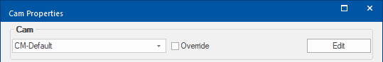
Multiple Cam settings can be stored and the settings used on the current drawing can be amended. Click on button to open properties.
The Mach.General > Const page allows you to determine what construction method is used for each component. Where required, it would need to be changed to 'Cam'. Setting up cams is a two step process - see Using and Setting up CAMS topic.More on Cam Button and Editing Properties
Use the drop list to select the required cam settings for the current drawing from those stored - in this case CM-Default.
Cam Properties - Click to Expand
Override allows these stored settings to be edited for the current drawing.
Import provides the ability to import settings from a downloaded file.
The Edit button is for editing the stored settings. It opens another Properties Inspector, shown below, on which you can change your cams as required or use the New button to create new setting. Use the Del button to delete/remove cam settings.
When 'Editing' the stored values, there are also the added options of Hardware Table and Hardware Key. These allow the entry to be linked to hardware tables found in <your CabMaster folder>\Table\Hardware\Cam\ folder.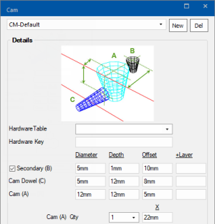
Cam Form Editor - Click to Expand
Secondary (B) : The offset from the centre of the Cam (A) hole.
Cam Dowel (C) : The offset is from the top of the machined face in which the large Cam (A) hole is drilled.
Cam Dowel Routing Map : Routing toolpaths, such as Peanut Connectors are supported, where traditionally a drill would have been used. This provides the ability to 3D route at Cam drill points. See note below.
Cam (A) : The offset is from the edge of the material.
+Layer : This is an extension to the machining Layer name defined for these steps. For example, if the defined layer name for the Cam(A) holes was 'CamLarge' and its +Layer was '-35mm' then the layer name used would be 'CamLarge-35mm'.
Cam(A) Qty : The number of the Cam(A) the large holes required.
Offset(X) : The spacing between their centre's as shown in the diagram.
The Offset is measured from the edge of your board to the centre of your cam.Cam Dowel Routing Map : If it is not blank the 'CamScrew' machining ('CamSmall' on Cams and 'Shelf' on Shelf Supports) is no longer a drilled hole, but is substituted by the routing layer it defines. Therefore, if used this field must contain a valid routing map.
As the correct definition of this map is essential it is recommended that you contact our CabMaster Support Team for assistance.
An example of a routing map is the 'Peanut-1' connectors defined under the Cams, where the routing map is...
Multiple Cam Bolts settings can be stored and the settings used on the current drawing can be amended. Click on button to open properties.
More on Cam Bolt Button and Editing Properties
Multiple Cam Bolt settings can be stored in the same manner as the Cam settings.
Use the drop list to select the required cam settings for the current drawing from those stored. In this case CM-Default.
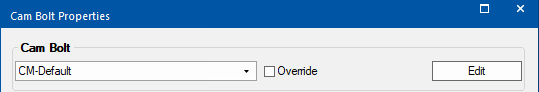
Cam Bolt Properties - Click to Expand
Override allows these stored settings to be edited for the current drawing.
The Edit button is for editing the stored settings. It opens another Properties Inspector on which you can change the Cam Bolt as required or use the New button to create new setting. Use the Del button to delete/remove cam settings.
When 'Editing' the stored values, there are also the added options of Hardware Table and Hardware Key. These allow the entry to be linked to hardware tables found in <your CabMaster folder>\Table\Hardware\Cam Bolt\ folder.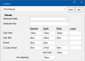
Cam Bolt Form Editor - Click to Expand
Cam Hole : The offset is from the edge of the part.
Cam Bolt : The offset is from the machined face of the part and it is drilled into the cammed part.
Dowel: An additional Dowel hole accompanying the Cam Dowel drilled into the edge of the cammed part and the adjoining part.
Cam Dowel Routing Map : Routing toolpaths, such as Peanut Connectors are supported, where traditionally a drill would have been used. This provides the ability to 3D route at Cam drill points. See note above.
+Layer : This is an extension to the machining Layer name defined for these steps. For example, if the Cam Holes default layer was "Cam" and the 'Layer+' was "34mm" then the resulting Layer would be "Cam-34mm"
Cam Dowel: Drilled in the adjoining part and offset to line up with the Cam Bolt.
from Cam : Distance away from the Cam Bolt along the edge of the part.
into adjoining : Depth drilled into the adjoining part.
Multiple Shelf Support settings can be stored and the settings used on the current drawing.
More on Shelf Support Button and Editing Properties
Multiple Shelf Support settings can be stored in the same manner as the Cam settings.
Use the drop list to select the required cam settings for the current drawing from those stored.
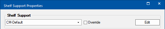
Shelf Support Properties - Click to Expand
Override allows these stored settings to be edited for the current drawing.
The Edit button is for editing the stored settings. It opens another Properties Inspector on which you can change the Offset and Diameter of your Shelf Support as required or use the New button to create new setting. Use the Del button to delete/remove cam settings.
When 'Editing' the stored values, there are also the added options of Hardware Table and Hardware Key. These allow the entry to be linked to hardware tables found in <your CabMaster folder>\Table\Hardware\ShelfSupport\ folder.Cam Dowel Routing Map : Routing toolpaths, such as Peanut Connectors are supported, where traditionally a drill would have been used. This provides the ability to 3D route at Cam drill points. See note above.
Cam : The offset is from the edge of the material.
+Layer : This is an extension to the machining Layer name defined for these steps. For example, if the default Adjustable Shelf Support hole's layer is "Shelf" and the '+Layer' was "3mm". Then the resulting layer name would be "Shelf-3mm".
Self Supports statistics can be included in reports - See Ancillary Settings.
The default can be overridden by the Drawer Runner Machining Tables.
These are usually overridden by the settings in the hinge tables.
Use checkbox to turn on/off machining for Handles.
The hole diameter is usually overridden by the setting in the chosen handle table.
The Depth default is 'Through' but there is the ability to specify that a handle is drilled from the back face and the drilling depth using the Handle Editor. This can be useful for machining of 'Lip Handles' that hook around the door to fasten from the Back.
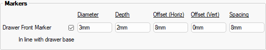
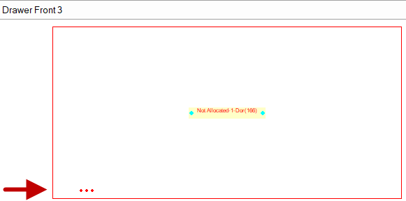
Drawer Front Markers are shallow drill holes made in the back of a drawer front to indicate which drawer it is. Drawers are numbered 1 to x from the bottom up. The markers are a series of holes representing the drawer number. One hole for drawer 1, two holes for drawer 2 etc.
These markers are placed in line with the bottom right hand side of the base of the drawer and can be offset from this position. So as to be hidden upon construction.
Example
Ticking the Use Drawer Front Marker check box allows you to define the size, offset and spacing.
The name of the machining Layer is "Marker". This can be changed if a "Marker" row is added to the layers table and set accordingly.
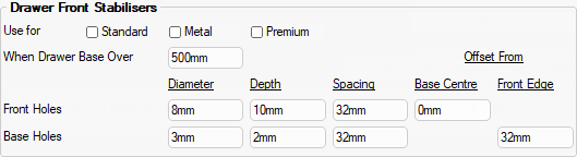
Drawer stabilisers are used in drawers over a given width to stop bulging. These can be added and applied to all drawers.
Example
The presence of the drawer stabiliser machining can be controlled for each drawer type i.e. Standard, Metal and Premium.
This option allows control of the Width the drawer base must be before they are automatically used.
The Depth, Diameter and Spacing of the holes can be controlled independently for the Front and Base.
Front Holes Base Centre - The Front holes are bored in line with the centre off the Base thickness plus the defined offset.
Base Holes Front Edge - The setback along the Base can also be varied.
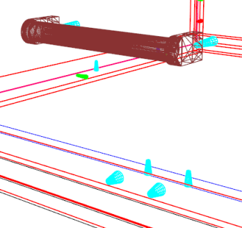
Dowel holes in the edge of a part might be drilled using a fixed dowel boring machine, side boring on a flatbed router or side boring on a flow through system. In addition, the correct pattern of corresponding holes need to be drilled in the face of adjoining parts.
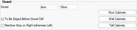
Diameter and Depth of the dowel tool.
Whether the edge tape is to be applied before drilling is done.
This checkbox defines from which end of an edge each hole configuration starts from.
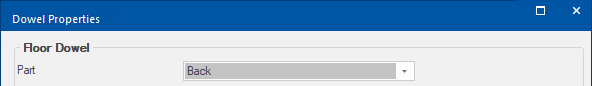
Clicking the Floor, Wall and Tall Cabinets buttons opens the relevant Dowel Properties dialog.
Click to view Floor Dowel Properties
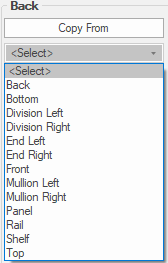
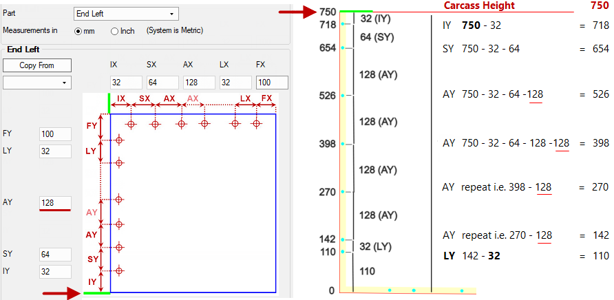
Part
On the Dowel Properties dialog, select a Part from the drop list.
Set the position of dowels using the diagram provided manually or by copying the settings from another Part.
Copy From
Select Part that you want to Copy From and then click the button.
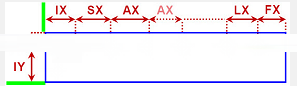
Dowel Hole Positions
The green marker on the image shows the end from which the 'stop' is positioned. So, if the stop is on the other end then the hole positions are simply mirrored.
Dowel Positions Horizontal
IX Initial Gap from the stop to an Initial Hole
SX Gap from that Initial Hole to the start of a Sequence
AX Gaps betweens holes in the Sequence
LX Gap from final Hole in the Sequence to a Last Hole
FX Final (minimum) Gap from the End of the part to the Last Hole
Dowel Positions Vertical
IY Initial Gap from the stop to an Initial Hole
SY Gap from that Initial Hole to the start of a Sequence
AY Gaps betweens holes in the Sequence
LY Gap from final Hole in the Sequence to a Last Hole
FY Final (minimum) Gap from the End of the part to the Last Hole
Based on the 'stop' position and, assuming the adjoining part is drilled with its machined face upward, the holes are drilled from the appropriate end as follows. At positions :-
For the Last hole : Initial Hole Gap plus Gap to Sequence plus multiple Sequence Gaps plus Gap to Last Hole (I + S + A*n + L)
Example of Dowel Drilling Pattern
In this example :-
- The Machine Stop position is set as on the left (
).
- The Left End is being machined from the inside face.
- So, when laid flat with it's machined upward, the top of the End will be on the left hand side.
- The drilling pattern, therefore, starts from it's top down.
With the Backs pinned on a 750mm high carcass and the machined from the inside face, the resulting Dowel drilling Pattern on the edge of the Back (for the End) is :-
Dowel Properties
Starting from the Top :-
- Initial Hole (IY) is the Carcass Height 750 - 32 = 718
- Then after the Start Gap (SY) = 750 - 32 - 64 = 654
- Next with a Sequence Gap (AY) = 654 - 128 = 526
- Repeat 3 above until there is insufficient space to have another drill hole, whilst leaving enough space for the Last Hole (LY = 32)
- Next with a Sequence Gap (AY) = 526 - 128 = 398
- Next with a Sequence Gap (AY) = 398 - 128 = 270
- Next with a Sequence Gap (AY) = 270 - 128 = 142
- Ensure you leave a Final Space (FY) from the end of the part i.e. 142 - (32 + 100) < 128