CM-Cabinets Library User Guide
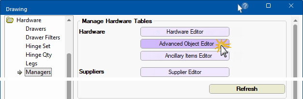
The Hardware > Managers page provides the ability to add and maintain advanced objects.
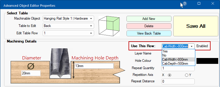
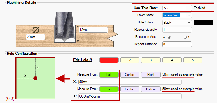
The Machining Details section provides the option for the user to edit the machining method for the selected row (default Table Row is 1).
The Ø character is widely known as the symbol for diameter. This sets the diameter of the hole to be made.
This is the Machining Hole Depth of that hole.
These are shown above as using a Length data type (so it’s showing with the mm units) but these two textboxes are actually using the String datatype which allows the user to enter a formula if they prefer.
When the Use this Row is Enabled then machining will be applied using this row and you will be able to set the Hole Configuration for individual holes.
Layer Name drop down is the name of the layer used by this row when taking the machining into EzyNest.
Hole Colour drop list is the graphical colour of the hole in 3D machining view.
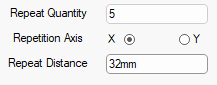
Repeat Quantity, Repetition Axis and Repeat Distance reference the repeating of holes. For example...
- the following would put 5 holes horizontally in a row, spaced 32mm apart.
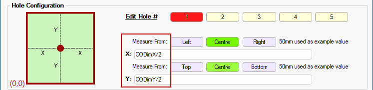
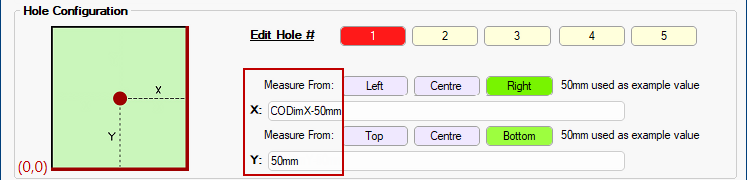
Machining tables have the option of up to 5 sets of holes in each row.
Edit Holes# and the Red button indicates which of the holes is currently selected for editing.
The Measure From buttons provide preset options.
The X and Y values correspond to the values to be stored in the X and Y columns in that table (of the selected row).
The diagram on the left provides a visual confirmation of the selection and therefore changes when Measure From buttons are pushed.
The origin point is always (0,0) i.e. X:0 and Y:0 which is the bottom left corner of the part. The red line provides a visual confirmation.
Hole #1 is placed X:50mm from
and Y calculated from the
(in this example as 50mm down from the top of the part).
Hole #1 is calculated for X :and Y:
Hole #1 is calculates X to be 50mm from the
and Y is placed 50mm from the