CM-Cabinets Library User Guide
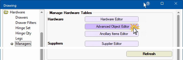
The Hardware > Managers page provides the ability to add and maintain advanced objects.
A 3D model can be included but it is not a requirement. An example of a 3D model with machining would be a hanging rail that can be machined into the carcass at both ends of the 3D model.
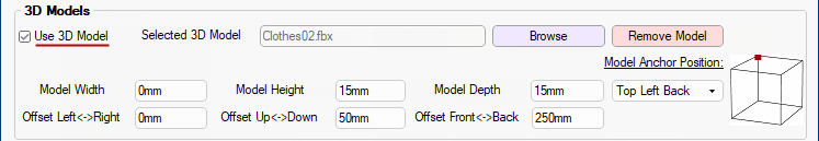
If the Use 3D Model is not checked, all 3D model options are disabled for the selected machinable object.
If you Use a 3D Model and, if any of the dimensions are set to size 0mm, then it allows the model to "fit to space" in the cabinet.
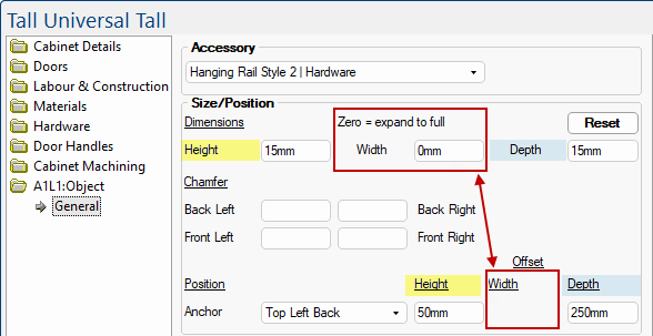
These defaults will be applied to the placed Advanced Object - click here for example.
Note that only the Offset for Height and Depth are made available for input, as the Dimension for Width is 0mm, therefore offset is not applicable.
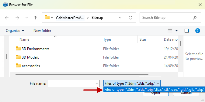
The Browse button will you to search for a 3D model to use by presenting a File Open dialog. By default it will start in <your CabMaster>\Bitmap folder but you can select a model from anywhere on your PC.
Example of available file types and location of Hanging Rail models
Model formats can be in any of the formats that CabMasterPro uses i.e. 3DM, 3DS, OBJ, FBX, STL, DAE, GLTF, GLB, or SKP.
Click on the image to view available Hanging Rail models...
Click to view ...3D Models\Accessories\Closet Items\Clothes
The Remove Model button will remove the reference to the 3D model from the tables, but will not delete the model from the PC.
The Model Width, Height and Depth values are the default dimensions of the 3D model.
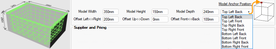
The following screenshot shows the wire basket with the imaginary bounding box, which is just the overall size of how much space is taken up by model, as a maximum length in all three dimensions.
The Model Positioning Offsets are default positions being applied to a model in relation to the model's "bounding box".
The Offset values will move the origin point of the model from the corner indicated by the Model Anchor Position drop list and confirmed in the diagram.
- If the Width Offset Left<->Right value is set to 200mm;
- and the Depth Offset Front<->Back value is set to 100mm;
- with the Model Anchor Position set to Top Left Back
In the above example, when the model is positioned in a cabinet, even though the ‘container’ of the model is in a set position, the model would be shifted 200mm to the Right (when front-facing the model) and 100mm forward.
Negative values are valid here, to move the model in the opposite direction. If, in the above example, the Width Offset Left<->Right is given a value of -200mm (i.e. a negative value ) the model would be shifted Left.
The 'Machinable Object' in the CM-Parts library can be used to just display a model on the drawing.
The Dimensions and Position Offsets are applied as shown.

 accessed from the Insert tab), with the exception that both reference 3D models - in that sense it is possible to get a size of a 3D model by using the 3D Model tool before going into the Hardware > Advanced Object Editor, so you know what sizes should be set.