CM-Cabinets Library User Guide
Robe Doors can be individually controlled at cabinet level and the defaults can be set on the Materials-Advanced > Robe Door page of the Catalog/Drawing Properties.
This cabinet is just the Doors, tracks and jambs that can be used in front of other cabinets or in between walls.
 Watch the Video which takes a quick look at the Closet/Robe Door options.
The Closet/Robe can include up to 6 hinged or 6 sliding doors and include the hardware for tracks and runners.
Material Datasource : CM-RobeDoors Datasource sample materials are also available from the CM-Default Datasource. This allows for the option of using the CM-RobeDoors and/or add new materials to your CM-Defaults (Materials.qlt). See also Job Setup > Job Defaults for Jamb/Plate Widths.
Doors are made up of a combination of parts and explanatory images are provided on most pages e.g. Options > Jambs page.
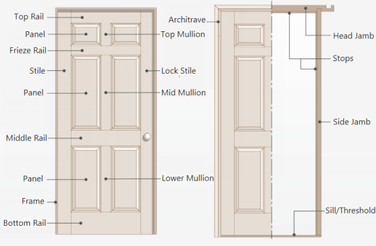
Rail : Horizontal pieces that connect the stiles.
Stile : Vertical pieces that run the full height of the door, one on each side.
Panel : Flat or raised sections that fit within the frame created by the stiles and rails.
Mullion : Seam that separates individual panels or frames of a door when combined. Sometimes called a mull for short.
Jamb : A door jamb is a part of the frame that surrounds the door slab. Commonly includes two side jambs and one head jamb i.e. upper horizontal portion of a frame. Jambs may feature a stops, a strike plate, and hinges.
Sliding Frames : A visible frame around glass panels that provide structural support and house the door's sliding mechanism.
Plates : Pieces that go above and below the door onto which the track fixes, used only when required, e.g. there may not be one at the bottom and the track fixes to the floor.
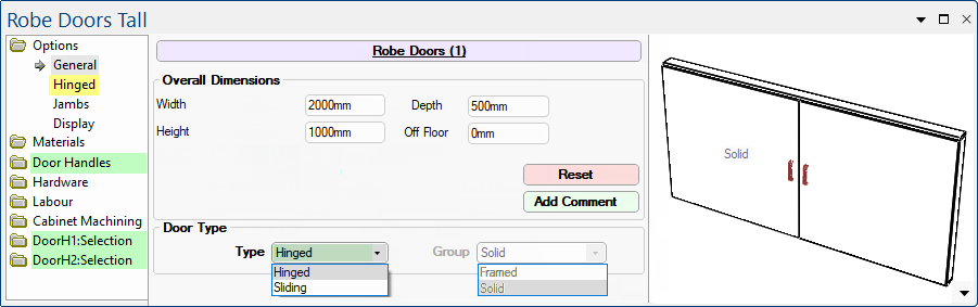
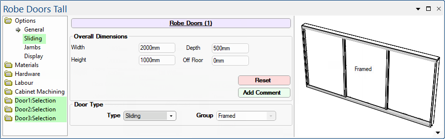
This is where the Overall Dimensions and Door Type can be selected here using the drop list available.
The default Door Type and corresponding materials are defined on the Materials-Advanced > Robe Door page of the DrawingProperties.
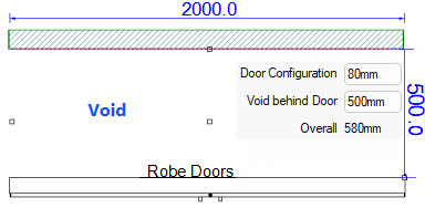
Depth of the robe itself includes a void behind the doors to the back of the object as a whole. This is to allow the doors to be positioned at a given distance from another object such as a wall. Other cabinetry can be placed inside the void.
Categories (highlighted in green) and Page options (highlighted in yellow are dependent on the Door Type selected.
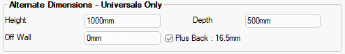
Alternate Dimensions set on the Job Setup > Job Defaults page of the Drawing Properties will be applied for the Robe Doors and can be overridden at cabinet level.
Follow these links for complete discussions on related topics.
- For Hardware and Cabinet Machining categories, see topics under Cabinet Properties.
- See Handles Door & Drawer of the Catalog/Drawing Properties for more on the Door Handles category.
- See Pricing Labour using Tables : Tutorial 3 for more on the Labour category.
See also the Hardware > Robe Track page of the Drawing Properties.
A hinged door is where the door panel is affixed to the frame with hinges on one side, allowing it to swing inwards or outwards.
The options on the Hinged page allow you to...

See Cabinet Machining > Hinging page discussed below.
Defaults are set on the Construction Robes > Door Configuration page and the Mullion Reset * buttons reapplies the Offset settings of the Mach.Shelf/Mullion > Mullions page of the Drawing Properties.
The DoorH1:Selection (etc) and Materials Category allow you to customise the materials for all door parts.
In the following example, only 2 doors have been added and corresponding Door 1 and Door 2 options are made available.
- Selection categories, highlighted in yellow, contain the options to customise materials for individual doors (click on image to view).
The Materials > Doors page allows you to override Materials-Advanced > Robe Door page of the Drawing Properties. To allow materials for each Hinged door part to be customised separately, extra categories are made available i.e. DoorH1 : Selection and DoorH2 : Selection

Click to view DoorH1 : Selection of materials
Hover cursor over edit boxes for descriptive comments e.g.refers to the top gap of Door 2.
Sliding doors have one or more door panels that open by gliding on a track.
The options on the Sliding page allow you to...
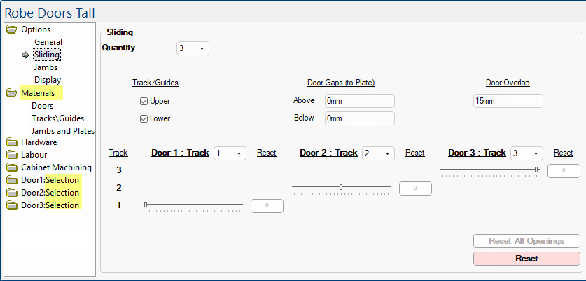
In the following example, only 3 doors have been added and corresponding Door 1, Door 2 and Door 3 options are made available. Selection categories, highlighted in yellow, contain the options to customise materials, (click on image to view materials for Jambs and Plates).
Click to view materials for Selection > Jambs and Plates
Extra categories are made available i.e. Door1:Selection etc. to allow materials for each sliding door part to be customised separately.
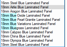
Sliding Frame material has a Filter feature which allows you to search for your specific criteria e.g. 18mm or Blue (see note).
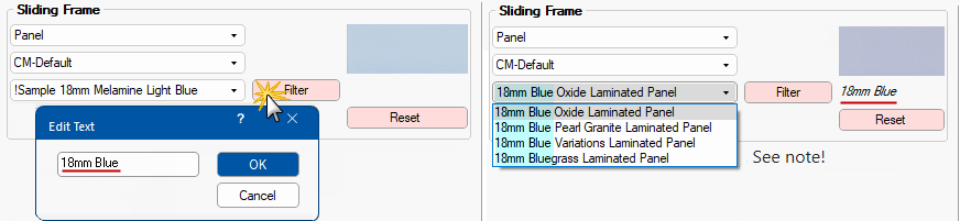
Click to view Filter for Sliding Frame using both CM-Default and the CM-RobeDoors materials
The Filter feature is currently limited to single phrase/word e.g. 'Blue' will find all 16mm and 18mm materials that have the specified word in the description.
The example above uses 2 words i.e. 18mm Blue but as you can see this limits the result.
Individual robe doors can be opened or closed using the track sliders.
Defaults for Gaps are set on the Construction Robes > Track Configuration page of the Drawing Properties.
The number of tracks sliders provided is dependent on how many sliding doors are selected.
In this example, there are 6 sliding doors and therefore 6 tracks. Watch the video below that discussed these.
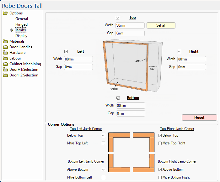
A door jamb is a part of the frame that surrounds the door slab.
The options on this page allow you to configure the jambs overall and individually. Explanatory images are provided as an aid.
The Reset button will revert the Jamb and Plate widths to the dimensions set on the Job Setup > Job Defaults page.
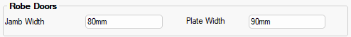
See Job Setup > Job Defaults for setting the defaults for the Jamb Width (Left and Right) and Plate Width (Top and Bottom).
Job Setup > Job Defaults - Click to Expand
Click to view Materials-Advanced > Robe Door Jambs & Plates page of the Drawing Properties
Defaults are set on the Construction Robes > Jamb Configuration page of the Drawing Properties.
Materials at cabinet level are set on the Materials > Jambs & Plates page.
Drawing Properties are set on the Materials-Advanced > Robe Door Jambs & Plates page (click image above to view).
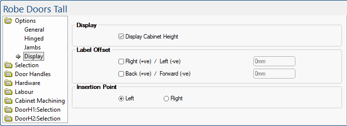
The options on the Options > Display page allow you to customise how cabinet labels are displayed on your drawing.
Shows the cabinet height on the Plan.
 For this to work, the corresponding option must be also be turned on in the Display > Options page of the Drawing Properties.
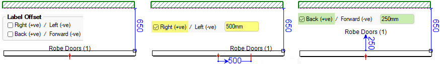
Label Offset moves the cabinet label right/left or back/forward dependent on whether the measurement is positive or negative, as shown.
Insertion Point is the distance from the floor to the bottom of the robe door cabinet.
Fixed Left or fixed Right radio buttons allow you to select the insertion point. Usually the cabinet is attached via the back Left corner, as you work left to right placing cabinets along a wall. (The back is the reference point where a cabinet is attached to the wall).
Sometimes it is more appropriate to work right to left, and so the Right hand side insertion point can be set for that. (However, snapping often takes care of you, so you can still work right to left even if the insertion point is on the left).
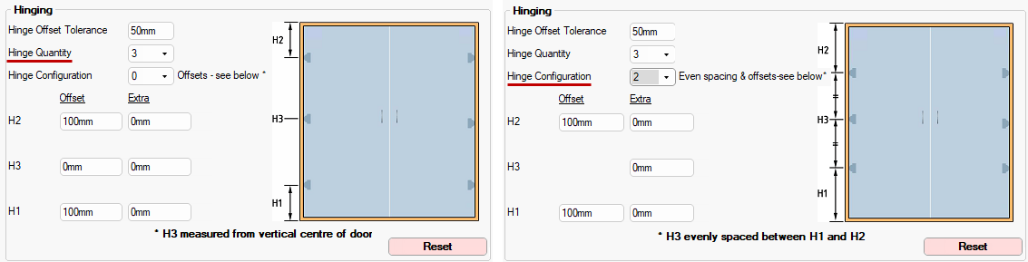
The Cabinet Machining > Hinging page provides the ability of setting the number of hinges. Two, three, four or five hinges can be placed on each door, dependent on the height of the door. The heights are all based on the position on the door and are to the centre of the hinge cup hole.

The distance of the upper (e.g. H2) and lower hinges (e.g. H1) are from the top and bottom of the door.
The centre hinge (H3) option provides the ability to offset the position of the central hinge of a 3 or 5 hinge door up or down. A positive (+ve) value moves the hinge up and a negative (–ve) moves it down.
The hinging image will automatically adjust to reflect Quantity and Configuration.
Defaults are set on the Construction Robes > Door Configuration page of the Drawing Properties.
A Minute with Mike : Take a look at our Closet/Robe Door options, made available in the version 12 update of CabMasterPro. [2:30 mins]