CM-Cabinets Library User Guide
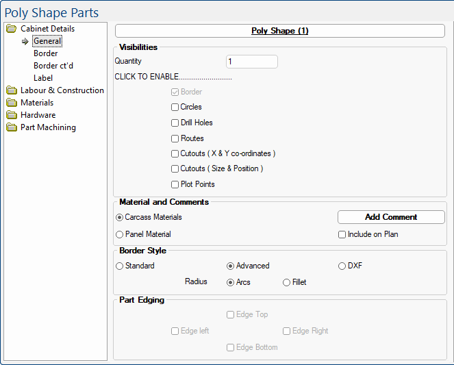
The Cabinet Details > General page gives the initial setup options for what you would like to do for the inner part of the Poly Shape (Visibilities), as well as providing options of how you would like to edit the part (Border Style).
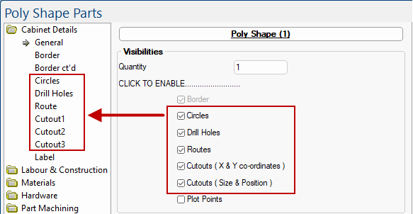
The check boxes are used to make applicable pages visible in the category tree. Compare the following image with above.
This check box is greyed out as the Border page is made available (visible) by default.
See topic on Poly Shape Border Settings.
The Circles page is intended for creating individual or a small number of repeated holes i.e. a circle cutout at a specified position on the part. An example of usage would be a hole for electrical wires.
Circles page
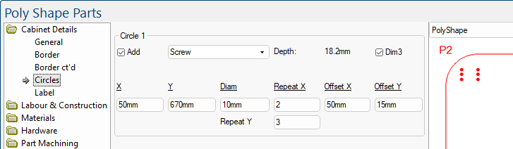
The Cabinet Details > Circles page provides the option of having up to 3 sets of circle cutouts to be applied to the shape. (Click on image).
Click to Expand
Add: Ticking this check box will make all the other options visible, as shown in the example above...
- the Layer name is Screw;
- as the Dim3 checkbox is ticked, the Depth is automatically set to 18.2mm i.e...
- the material thickness here it is 18.0mm carcass;
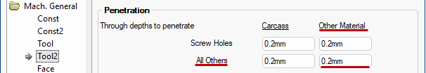
plus- the value set on the Mach.General > Tool2 page in the Drawing Properties which, in this example, the All Others/Other Materials value is 0.2mm.
Click to Expand
- If the Dim3 checkbox is unticked, a textbox will appear that gives you the option to enter your own value to define the cutting depth for the circle.
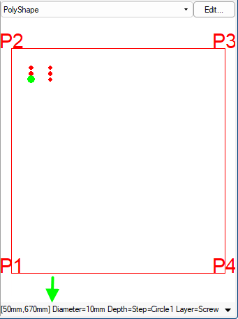
- The position of the initial hole is X:50mm Y:670mm with a Diameter of 10mm.
Example
The preview pane here shows the machining details of selected screw hole.
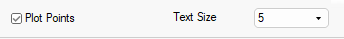
Plot Points in this example have also been turned on.
- Repeat X here has been set to 2;
- which creates 2 holes separated by the value entered in Offset X, i.e. 50mm.
- Additionally, as Repeat Y has been set to 3 and Offset Y has been set to 15mm;
- there will be also be 3 holes vertically that are measured 15mm apart.
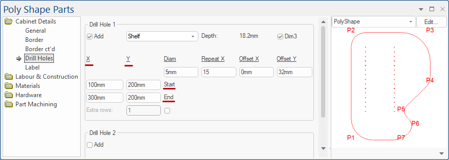
The Drill Holes page is specifically intended for creating at least two (2) rows of repeated holes i.e. repeatable straight lines of drill holes. An example of usage would be continuous shelf holes.
Drill Holes page
Add: Ticking this check box will make all the other options visible, as shown in the example above...
- X : Start specifies the distance of the holes from the left edge (measured from the 0mm mark);
- Y : Start specifies the distance that the holes will start from the bottom edge (also measured from the 0mm mark).
- X : End is the position of the right column of holes measured from the left edge;
- Y : End is the position of the right column of holes measured from the bottom edge.
- Extra Rows, if turned on, a third column of holes would be presented, measured in the exact centre, between the 2 existing columns.
- Changing this value will add more columns of holes, each evenly spaced between the initial left and right columns of holes.
The other options on this page are the same as for the Circles page.
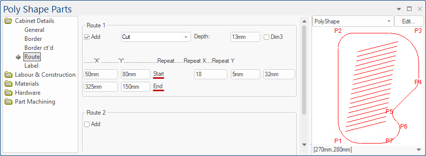
The Route page provides the option of multiple straight lines that can be routed. An example of usage would be air vents.
Routes page
The Route lines are positioned by the X : Start and Y : Start values, measured from the bottom left corner, and continue in a straight line to the location specified by the X : End and Y : End values.
The number of lines is specified by the Repeat value and are offset by the Repeat X and Repeat Y values.
All values are measured from the X:0mm and Y:0mm positions.As shown in the example above...
- the bottom route line starts at 50mm from the left edge and 80mm from the bottom edge;
- the line continues towards the right until it reaches 325mm from the left edge and 150mm from the bottom edge.
- This line is repeated 18 times, with each line positioned a further 5mm from the left edge, and a further 32mm from the bottom edge.
- Each line will be routed as 13mm deep (unticking the Dim3 checkbox provides the option of specifying a routing depth) and will be nested using the Layer name ‘Cut’.
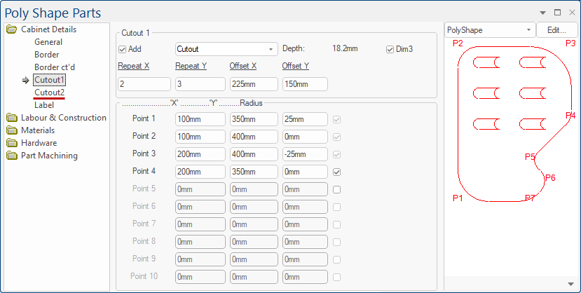
Using up to 10 plot points, for creating a cutout in the part by the X & Y coordinates.
Cutout1 page and Cutout2 page are identical, providing two iterations of the same option.
Cutout1 and Cutout2 pages
Looking initially at the bottom left of the 6 cutouts, this is set up in the same style as the Cabinet Details > Border page, which uses X/Y coordinates to position each corner of the cutout shape.
An outward-curved radius requires a positive value, and an inward-curved radius requires a negative value.In the above example...
- Point 1, the bottom left cutout starts at 100mm from the left and 350mm from the bottom and applies a 25mm outward-curved radius.
- Point 2 is also measured 100mm from the left edge and is 400mm from the bottom edge.
- Point 3 is 200mm from the left edge and 400mm from the bottom edge, with a 25mm inward-curved radius (requiring a negative value for the radius).
- Point 4 is 200mm from the left edge and 350mm from the bottom edge.
- A Repeat X of 2 has provided 2 columns of this same cutout shape, measured 225mm (Offset X) from the left edge of the bottom left cutout.
- Similarly, a Repeat Y of 3 has set this to have 3 rows of this same cutout shape, measured 150mm (Offset Y) from the bottom edge of the bottom left cutout.
The X and Y coordinates of the Points values are measured from the bottom left corner (X:0mm and Y:0mm) of the poly shape.
The Repeat's Offset X and Offset Y values are measured from the bottom left corner of the cutout shape that has been created by using the Points values (the exact position which is X and Y in the Point 1 row).
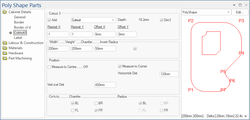
Create 4-sided shapes to be cutout in the part by provided the size and position of the cutout.
Cutout3 page
The Cutout3 page provides an alternative to Cutout1 & Cutout2 pages to create a cutout.
The Add, Layer, Depth/Dim3, and Repeat options are the same as discussed above.
In the above example...
- The Width (200mm) and Height (250mm) values specify the size of the cutout.
- The Chamfer (50mm) is the size of the chamfered corner to be applied (when the option is selected for that corner, more on that later).
- The check box to the right of Chamfer is to invert the radius.
- The check box is ticked, and as shown in preview pane, the upper left corner of the cutout has an inward-curved radius.
- If this checkbox was unticked, it would show an outward-curved radius instead.
Position
- The Measure to Centre check box sets the origin point of the cutout to the centre of the cutout.
- This would make the Vertical Distance and Horizontal Distance measure from the centre of the cutout.
- Alternatively, the Measure to Corner will set the origin point to the bottom left corner of the cutout shape.
- As shown above, this option is ticked and the cutout shape is being measured from is bottom left corner and is 400mm from the bottom edge of the poly shape (Vertical Dist) and 120mm from the left edge (Horizontal Dist).
Cnr's to Chamfer / Radius
These check boxes are for enabling the chamfer and radius for each individual corner of the cutout.
- BL is Back Left (Top Left);
- BR is Back Right (Top Right);
- FL is Front Left (Bottom Left);
- FR is Front Right (Bottom Right).
In this example, the Back Left (BL) and Front Right (FR) have the chamfer turned on. Also, the Back Left (BL) has the Radius enabled.
This does not create any shape on the part, but simply shows the direction which you would plot each point to create your desired shape.
When you tick the Plot Points check box...
The radio buttons allow you to select whether the poly shape will be made out of carcass or panel material.
These settings (and any changes) will be reflected on the shapes Materials > Panel page (click on image), defaults of which are set on the Job Setup > Materials page of the Drawing Properties.
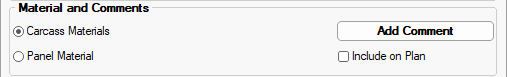
Click to view Materials category details and Drawing Properties
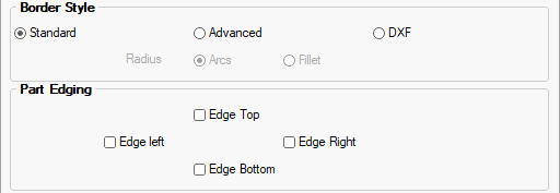
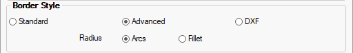
The radio buttons allow you to select the style of border. These settings determine what options are made available on the Cabinet Details > Border page.
Sets the poly shape to be a simple square or rectangle, with the size of the part specified on the Cabinet Details > Border page.
The option of Part Edging each side is enabled, as the part will have four (4) flat sides,
Specifies that the poly shape will be created by using up to 20 plot points, with the added option of applying radiuses.
Arcs are curved line pieces you draw. Often you are joining two points and you specify a radius for the arc.
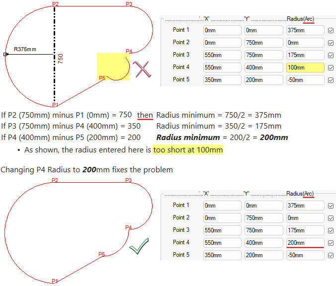
The minimum radius must be half the distance between one point and the next point.
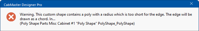
Radius 'too short' warning message
If the radius specified is so small that an arc cannot reach between points (e.g. Point 4 and Point 5) then a warning message will be displayed.
Fillets are arcs rounding off corners, typically 90deg corners but can be other angles (e.g. 135deg is not unusual).
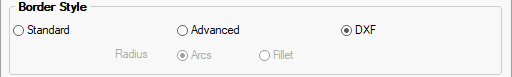
Gives the option of setting the poly shape to be the same shape provided by a DXF file.
The DXF file is selected on the Cabinet Details > Border page.