CM-Cabinets Library User Guide
The Cutout feature allows customers to add lettering and decorative cutouts to a cabinet part, by machining existing DXF files of outlines in repeated sets of up to ten (10) individual outlines. CabMasterPro will then seamlessly integrate with EzyNest to achieve the desired result.
The Cutout features allow you to use (1) Pre-Defined DXF files and/or (2) Pre-Set cabinet cutout configurations e.g. horizontal pipe chases.
 Watch the video below which demonstrates how to add pre-defined cutouts using DXF files. [2:22 mins]
Watch the video in the topic on Cabinet Cutouts which demonstrates how to create cutouts using the Enable Cabinet Cutout option. [1:48 mins]
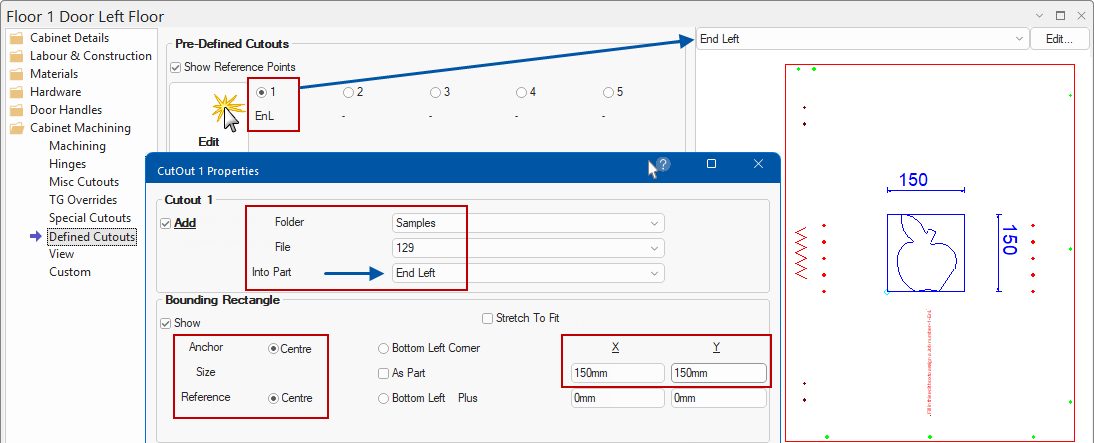
At Cabinet level each cabinet can have up to 10 cutouts which can be defined on the Cabinet Machining > Defined Cutouts page.
The Defined Cutouts page has 10 radio buttons representing the 10 cutouts and an option to show their anchor points. Each cutout can be associated with a different part (or multiples on the same part), which provides the ability to import DXF and/or QPF files into a parts DXF as a cutout.
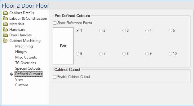
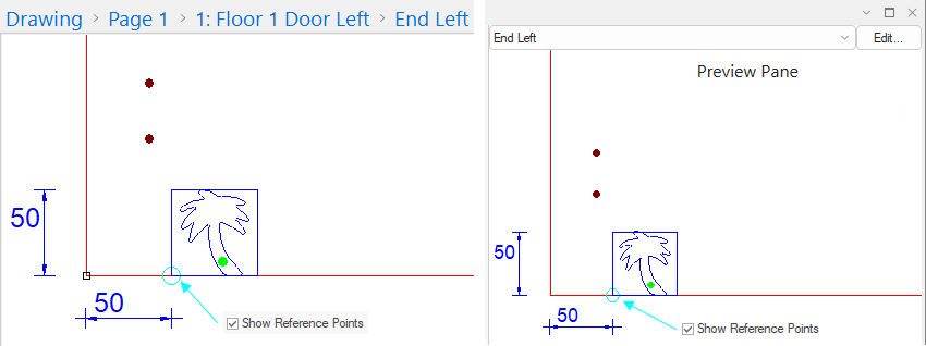
If ticked/enabled, a visual representation of the point at which the cutout is placed will be provided. Cutout design and placement will take place when you Edit the cutout.
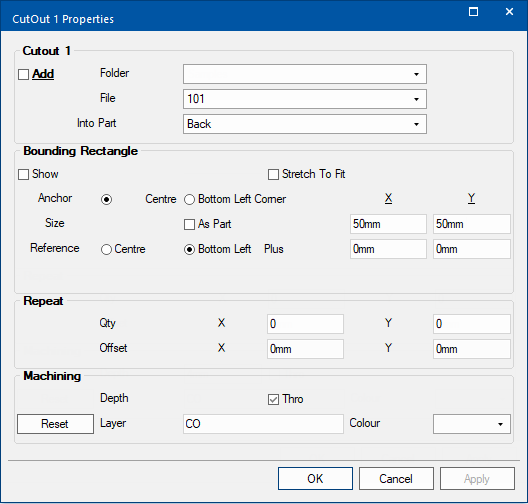
The referenced here confirms that the cutout is anchored to the bottom left corner and is 50mm in the X direction - discussed later in this topic.
Select a number and click on Edit button to open the Cutout Properties form, discussed below, where the cutout is defined.
Once a cutout is defined, the Part in which it will be cut is stated

Cutout 1 is the Part in which the cutout will be applied - Click to Expand
When this option is turned on, extra CabinetCutout pages are able to be accessed. Follow the links for a full discussion on each page.
- CabinetCutout:Quick Start - allows the user to quickly set the cabinet cutout into commonly used configurations.
- CabinetCutout:Position
- CabinetCutout:Materials
- CabinetCutout:Machining
A cabinet cutout lets you place a cutout with a full carcass anywhere in a cabinet e.g. pipe chases.

Enable Cabinet Cutout turned on - Click to Expand
Clicking on Edit button on the Define Cutouts page opens a Properties window (shown below) to allow you to define the cutout/s.
To locate information about any part of the following image,  click on the area of interest. See also topic on supplied DXF Samples.
Watch the video below which demonstrates how to add pre-defined cutouts using DXF files. [2:22 mins]
Whether or not the cutout is to be used on the selected cabinet area. See topic on supplied DXF Samples.
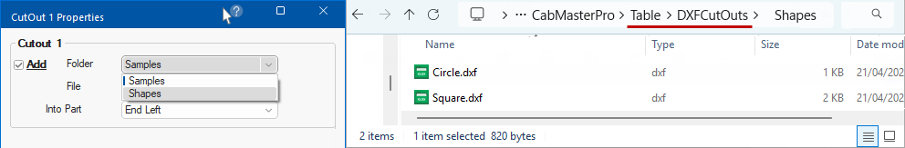
This is the location subfolder and file name of the required cutout.
The .DXF or .QPF files can be added to subfolders within the <your CabMaster folder>\Table\ DXFCutOuts folder where a number of samples are included by default.
Sample DXF files are provided by CabMaster Software™ which are used in this topic but you can create your own folders and DXF files for use.
See topic on Defined Cutout Samples for a complete list of supplied DXF cutout images together with the reference file numbers.
The cabinet part in which the cutout is to be made.
In the case of some parts, for example shelves and doors, the cutout will appear in all of them.
The Preview Pane automatically updates as cutout options are applied. Just remember to select the correct part to view - click here for an example.
Example of a cutout displayed in the Preview Pane which automatically updates as options are selected.
The Bounding Rectangle defines the extremes the cutout can fit into.
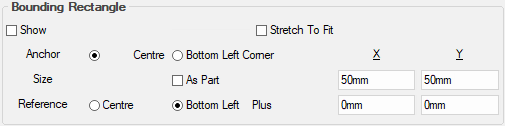
The Show checkbox is used to turn on/off the bounding rectangle.
Example of four (4) cutouts added to the End Left of a cabinet with the Grid turned on...
- staggered by 50mm starting from the Bottom Left Corner (Anchor);
- with Show Bounding Rectangle enabled;
- colours of cutouts changed to red and blue (for visual impact only);
- shows a reference point (shown in light blue).
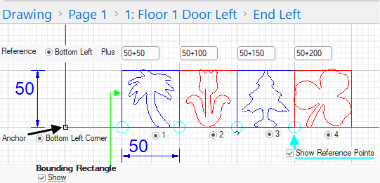
Click to view each of the four Cutout Property sheets that make up the above
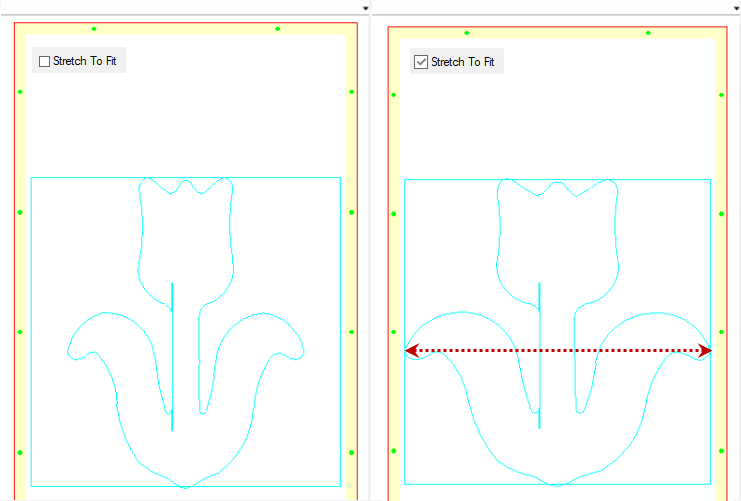
Fit both vertically and horizontally into the bounding rectangle, as opposed to proportionally sized (where it will expand until one point on the shape hits the edge of the box).
Example
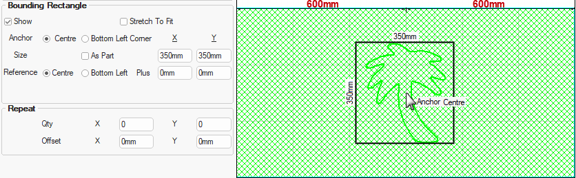
These examples use a shape (101.dxf) centred on a bounding rectangle of 450x450
The anchor refers to the datum point, either Centre or Bottom Left Corner by using the radio buttons.
Example with cutout with Show Boundary Rectangle and Anchor DXF to Centre
This example shows settings Show Boundary
The size of the DXF cutout, based on its bounding rectangle. Either As Part (the entire size of the part) or specified Size x:y dimension.
The reference is where on the part the anchor point is aligned to. This can be set at either Centre or Bottom Left of the part Plus a specified distance.
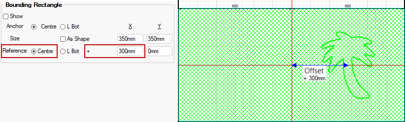
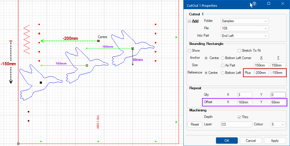
Example with cutout Offset from the Reference Centre
This example, Offsets the DXF cutout 300mm from the Reference Point (Centre).
The cutout outlines are placed within Bounding Rectangles which allows them to be sized.
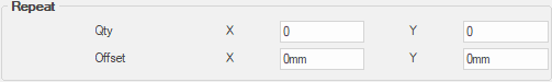
The Repeat options allow multiple cutouts at a specified Offset.
The position of the rectangle (Centre or Bottom Left) is defined as an Offset from the Reference Point.
In this example, the position of the three (3) birds the Reference Point is Centre.
Click to view another example using Reference Bottom Left
Layers provide a way to separate design information and toolpaths into groups and can be displayed in different colours to help distinguish different parts of the design.
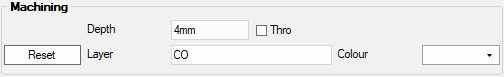
The Depth of each cutout can be controlled by either selecting a required Depth or using the Thro checkbox, which if ticked, automatically adjusts with the thickness of the material.
The default Layer name (important for use with EzyNest) and DXF Layer Colour can be specified in the Drawing Properties - click image below to view.
The default comes from the table located in the <your CabMaster folder>/Table/Machining/Layers folder.
The default layer name has the depth appended to its name if a specific depth is specified.

Layers table states defaults set on the Mach.General > Tool page - Click to view
A Minute with Mike : This video demonstrates how to add pre-defined DXF cutouts using our supplied sample files but you can create your own.
We're pretty sure that a bird-shaped cutout (109.dxf) is one of the less commonly selected cutouts, so click here to see the full range of samples that you can use.