CM-Cabinets Library User Guide
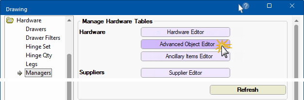
The Hardware > Managers page provides the ability to add/maintain a 3D model with optional machining.
For a more detailed discussion on each of the option groups, follow the links...
These 'Advanced Objects' are understandable by breaking it down to one section at a time.
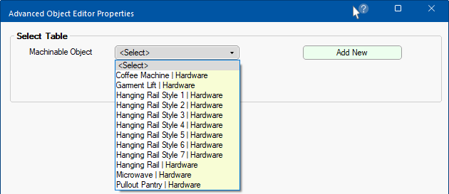
You start by selecting or creating a new "Machinable Object", then...
Machining, model or extra data are not required i.e. simply enter details that you need. This means that if you just want a 3D Model, only complete the 3D model section and leave holes blank.
Once all details required are entered, ensure that you click on the "Save All" button.
This "Machinable Object" will now be available for use in all Universal cabinets - discussed below.
Use the Advanced Object Editor button to launch Advanced Object Editor dialog which initially provides the ability to...
For a more detailed discussion, see the topic on Advanced Object Editor : Add New or Delete
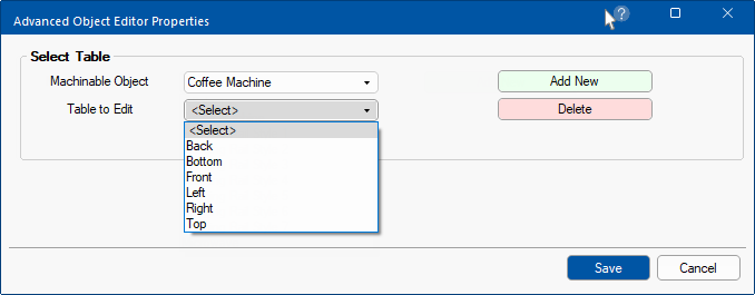
The applicable hardware table for the selected Machinable Object can be located using the naming convention used in the drop list.
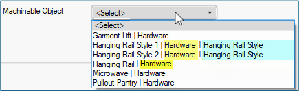
This naming convention allows new hardware packages to be included in a library update without overwriting a customer’s existing table i.e. Hardware.qlt
See also the discussion on tables added when a new item is created.
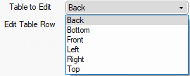
The Table to Edit links to six of the tables shown, in the folder \Table\Machining\Accessories\[selected Machinable Object]\.
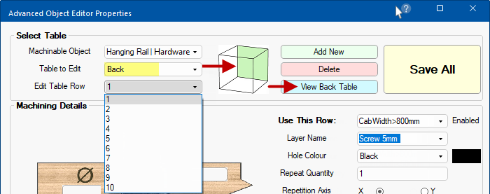
Once the Table to Edit (e.g. the 'Back' table) has been selected the...
 green shading;
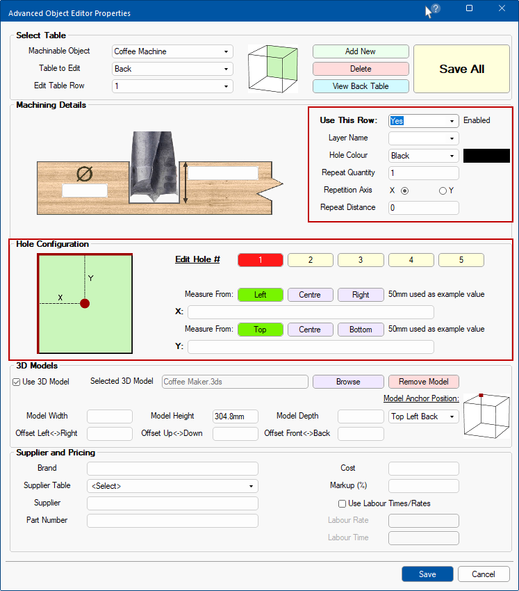
When the Table and Row are selected, you will be able to define the Machining.
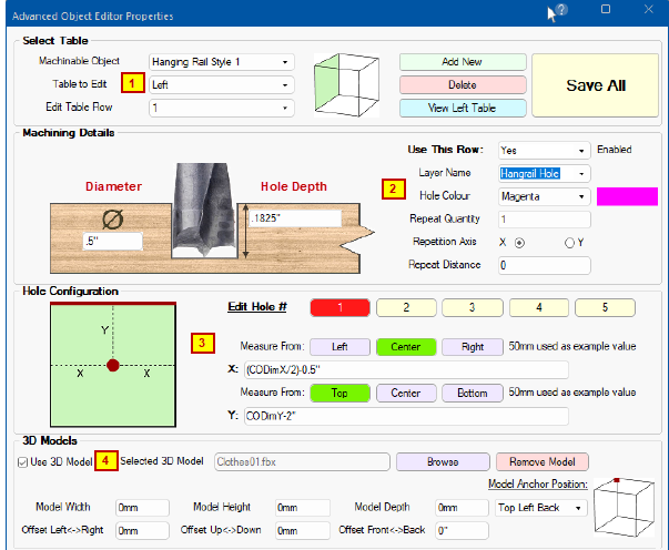
A 3D Model is optional, however, the purpose of the Advanced Object Editor is to facilitate machining to support a 3D model. If Use 3D Model is unticked, all 3D model options will be disabled for the selected Machinable Object. For a detailed discussion, see topic on 3D Models.
If you are using a 3D Model, ensure that you correctly state the dimensions i.e. Model Width, Height and Depth.
When Use this Row is Enabled you will have the extra ability to set the Hole Configuration for individual holes.
 For a detailed discussion, see the topic on Advanced Object Editor : Machining and Holes
Now we will discuss how to use an advanced object (after it has been created as per above) and placed in a Universal cabinet.
In this example, we have placed a Tall Universal on our job/drawing and then...
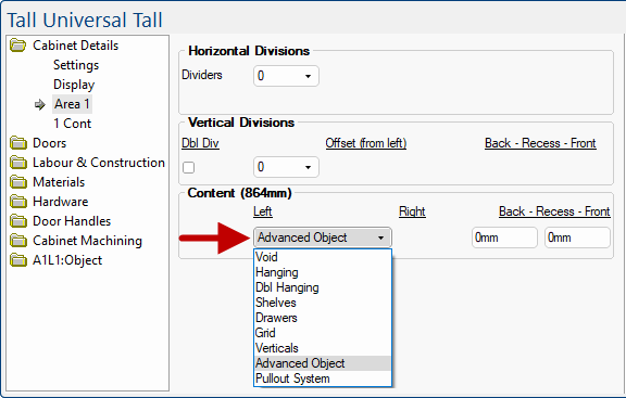
On the A1L1:Object > General page, select the required Accessory using the drop list.
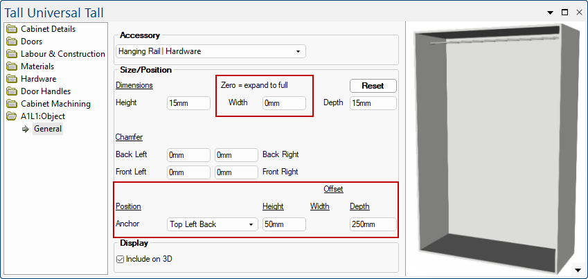
Then set the values on the A1L1:Object > General page to make the model work. On the General page above...
the default Width has been changed to 0mm so that the accessory fills the space;
the Offset Height has been set to drop the 3D Model hanging rail down by 50mm;
the Offset Depth has been set to bring the hanging rail forward by 250mm.
We now have a 3D Model with associated drilling available for re-use as required i.e. the hanging rail will have holes drilled as required and the 3D model is showing a rail.
The Position and Offset defaults can be set using the Advanced Object Editor in the 3D Models group (highlighted in green above) and/or overwritten at cabinet level. For a detailed discussion, see the topic on 3D Models.
Pricing for this example will be covered in the topic on Pricing Advanced Object.