CM-Cabinets Library User Guide
At Cabinet level you can amend cabinet dimensions and other general attributes on the Cabinet Details > General Settings page. The height and depth defaults are set in the Job Defaults of the Catalog/Drawing Properties.
The options discussed here cover the typical Floor, Wall and Tall cabinets. As the construction of individual cabinets vary, the available options will also vary and are not all covered in this topic.
Universals and Robes are discussed in a separate section and the Floor Multi cabinet in a separate topic, as this is similar to the customisable Universal Cabinet.
Corner Fillers (Floor/Tall/Wall) have extra Placement options to include an overlap of the panels, allowing for easier installation and assembly.
 click on the area of interest.
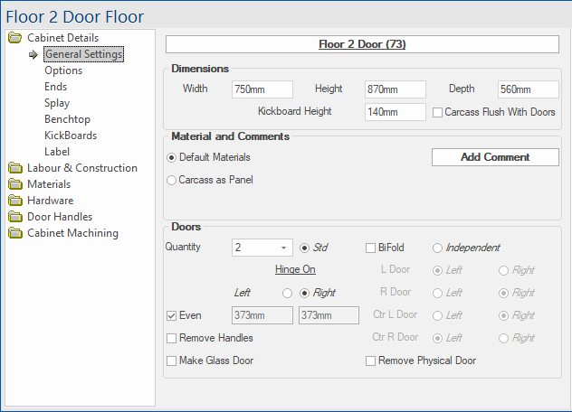
This button displays the name of the cabinet and the Cabinet ID (number CabMaster automatically assigned when placed in drawing), if the Show Cabinet ID checkbox is enabled on the Display > Options page of the Drawing Properties.
The Local Properties dialog is opened by clicking on this button - follow link for full discussion.
The Cabinet Information button is also available on the Quick Access Sidebar.

If cabinets are deleted during/after placement, the Cabinet ID may need renumbering.
To do this, use the Renumber commands  on the Insert tab of the CabMasterPro command ribbon.
Width, Height and Depth of cabinet and kickboard can be customised.
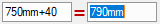
You are able to do math in the input fields e.g: if you type +40mm in the Width edit box which is currently displaying 750mm then the result is 790mm.
Floor carcass Height typically includes the kickboard height i.e. If the kickboard height is 140mm and the cabinet is 730mm then the actual height from the floor to the top of the carcass is 870mm.

| Cabinet | Options based on Cabinet Type |
Click on Image |
| Floor Door | Checkbox option to make the Carcass Flush with Doors. | |
| Floor Drawer |
Checkbox option to make the Carcass based on Interior Height and an edit box which is made available when turned on to allow the adjustment of the interior height. |

|
| Floor Tall | Checkbox option to make the Carcass Flush with Doors and checkbox option to make the Lower Carcass based on Interior Height |

|
| Wall |
Ability to override Height Options set on the Job Setup > Defaults page Off Bench specifies the height of the wall cabinets off the bench and if selected the Height Off Bench edit box is made available. These options also affect the Height dimension of carcass as this is automatically adjusted and greyed out. Height to Top, if adjusted, also will affect the Height dimension. |

|
Materials for current cabinet can use the Default Materials or can be changed to Carcass as Panel. See Job Setup > Materials page.
The Add Comment button opens a text box which allows you to make comments that will be displayed in reports such as Column Board Report by Cabinet.rpt
The quantity of Doors or Drawers, as relevant to selected cabinet, can be adjusted.
| Cabinet | Options based on Cabinet Type |
Click on Image |
| Floor Door |
Door type options are ...
See topic on Cabinet Independent Hinging for examples. Checking the Make Glass Door option is purely graphical for 3D viewing, removing the doors centre panel and replaces it with a rectangular glass design. It is available for most door styles but cannot be applied to a door that has a Farmers or DoorMaster LT style. This option is mainly graphical but if machining is required see Mach.General > Cutout-Doors page. |
|
| Floor Drawer |
Use Full Door for Drawer Fronts sets the front material as the 'drawer bank' default (set elsewhere). There is also an option to 'Add Doors' which will make the related Quantity, Hinge and Glass Door options available. Advanced drawer quantity options can be accessed by clicking the Quantity |

|
| Floor Tall |
Ability to have an Upper and Lower section, if quantity of doors is "1" then Pull option is made available. Door can be BiFold and the Hinges can be positioned Left or Right or door can be removed completely. |

|
| Wall | Much the same as Floor, except you have the added option to have Lift door. |

|


 button next to drawer quantity. This will open a separate window containing some alternative sizing and quantity options for the drawer front configurations. See topic